Download de presentatie
De presentatie wordt gedownload. Even geduld aub

1
Input/Output Invoer/Uitvoer
ppt_aa1_p09_digital_io_v4-0_nl_0508

2
I/O mogelijkheden Maakt het mogelijk om camera’s met bewegingsdetectie te integreren in beveilgingssystems De I/O maakt het mogelijk om netwerkvideo te combineren met specifieke toepassingen “Met I/O kan een camera schakelen of worden geschakeld – alles wat nodig is, is een signaal”

3
Sluit de Network camera/video server aan:
Input Deur contact Passive IR beweginsdetector Glasbreek sensor Schok sensor Geluidsensor Output Alarm centrale Sirene Deur slot Rookgenerator Koffie machine

4
Typisch I/O gebruik – Integratie met alarm
Camera met input/output porten Alarm Controle Centraal Venster of deur sensor Video opname Server

5
De I/O port op een Axis 211 Netwerk Camera
Pin Functie Beschrijving 1. Ground (-) Common ground of the camera 2. Aux. DC Power Input Alternative spanningsaansluitng voor de camera. Kan ook spanning afgeven tot 100mA, uitgezonderd bij gebruik van PoE 3. Digital Input Digitale input, verbinden met pin 1, koppeling naar aarde 4. Transistor Output Aanstuurbare digitale output. Open collector, NPN transistor Max. 100mA, Max. Voltage 24V DC 1 Ground (GND) 2 Auxiliary DC Power Input 7-20 VDC/min 7W. Electrically connected in parallel with the PS-k power connector, this pin provides auxiliary connector for mains power to the unit. If the unit is powered via this pin, a fuse should be used (rating: 1A Slow). This pin can also be used to power auxiliary equipment, max 100mA, but note that this is not possible when the AXIS 211 is powered by PoE. 3 Digital Input Connect to GND to activate, or leave floating (or unconnected) to deactivate 4 Transistor Output With a maximum load of 100mA and a maximum voltage of 24V DC, this output has an open-collector NPN transistor with the emitter connected to pin 1 (GND). If used with an external relay, a diode must be connected in parallel with the load, for protection against voltage transients.
 Common ground of the camera. 2. Aux. DC Power Input. Alternative spanningsaansluitng voor de camera. Kan ook spanning afgeven tot 100mA, uitgezonderd bij gebruik van PoE. 3. Digital Input. Digitale input, verbinden met pin 1, koppeling naar aarde. 4. Transistor Output. Aanstuurbare digitale output. Open collector, NPN transistor. Max. 100mA, Max. Voltage 24V DC. 1 Ground (GND) 2 Auxiliary DC Power Input VDC/min 7W. Electrically connected in parallel with the PS-k power connector, this pin provides auxiliary connector for mains power to the unit. If the unit is powered via this pin, a fuse should be used (rating: 1A Slow). This pin can also be used to power auxiliary equipment, max 100mA, but note that this is not possible when the AXIS 211 is powered by PoE. 3 Digital Input. Connect to GND to activate, or leave floating (or unconnected) to deactivate. 4 Transistor Output. With a maximum load of 100mA and a maximum voltage of 24V DC, this output has an open-collector NPN transistor with the emitter connected to pin 1 (GND). If used with an external relay, a diode must be connected in parallel with the load, for protection against voltage transients.")
6
Schema

7
Aansluiting van een alarmsysteem
N.C. – Normally Closed Closed - Normal Open – Alarm!! N.O. – Normally Open Breaking the Circuit Other than the family dog, the most basic burglar alarm is a simple electric circuit built into an entry way. In any circuit, whether it's powering a flashlight or a computer, electricity only flows when you give it a path between two points of opposite charge. To turn the electricity on or off, you open or close part of the circuit. To open or close a flashlight circuit, you simply throw a switch. In a burglar alarm, the switch detects the act of intrusion -- opening a door or window, for example. These sorts of alarms are divided into two categories: In a closed-circuit system, the electric circuit is closed when the door is shut. This means that as long as the door is closed, electricity can flow from one end of the circuit to the other. But if somebody opens the door, the circuit is opened, and electricity can't flow. This triggers an alarm. In an open-circuit system, opening the door closes the circuit, so electricity begins to flow. In this system, the alarm is triggered when the circuit is completed. There are a number of ways to build this sort of circuit into an entry way. Closed circuits are normally a better choice than open circuits because an intruder can deactivate the open circuit by simply cutting the connected wires. A magnetic sensor in a closed circuit consists of a few simple components. For the most basic design, you need: a battery powering a circuit a spring-driven metal switch built into a door frame a magnet embedded in the door, lined up with the switch a separately-powered buzzer with a relay-driven switch. When the door is closed, the magnet pulls the metal switch closed so the circuit is complete. The current powers the relay's electromagnet, so the buzzer circuit stays open. When you move the magnet by opening the door, the spring snaps the switch back into the open position. This cuts off the current and closes the relay, sounding the alarm. You can also build this sort of system into a window. If an intruder pushes a window open, the magnet slides out of line with the switch, and the buzzer is activated. Another simple burglar alarm uses a small button as the switch. The button is embedded in the door frame, so closing the door pushes it in. When somebody opens the door, the button is released, changing the circuit and sounding the alarm. With just a battery and buzzer, these designs make for fairly flawed security systems. After all, the burglar only needs to close the door again to turn the buzzer off. That's why most modern burglar alarms incorporate another piece into the circuit -- the control box. The control box is hooked up to one or more alarm circuits, but it also has its own power supply. It monitors the circuits and sounds the alarm when they are closed or opened (depending on the design). But once the alarm is triggered, the control box won't cut it off until somebody enters a security code at a connected keypad. For added security, the control box is usually positioned in an out-of-the-way spot, so the intruder can't find it and attempt to destroy it. Using this basic concept, you can create all sorts of alarm systems. Just imagine what a burglar might do to break into a house, and then turn that action into the circuit switch. For example, an intruder might break through a window, so you could make the glass itself a circuit. The easiest way to do this is run a current through a thin line of foil wire affixed to the surface of the glass. If a burglar breaks the glass, the circuit is broken, and the alarm is triggered. Floor mats are another simple option. A basic floor mat uses an open circuit design with two metal strips spaced apart. When somebody steps on the mat, the pressure pushes the two metal strips together, completing a circuit. All of these circuit systems are best for guarding the perimeter of a house or business -- the points an intruder would enter the building. In the next section, we'll look at systems that detect an intruder once he or she has already made it inside. Open - Normal Closed – Alarm!!
. But once the alarm is triggered, the control box won t cut it off until somebody enters a security code at a connected keypad. For added security, the control box is usually positioned in an out-of-the-way spot, so the intruder can t find it and attempt to destroy it. Using this basic concept, you can create all sorts of alarm systems. Just imagine what a burglar might do to break into a house, and then turn that action into the circuit switch. For example, an intruder might break through a window, so you could make the glass itself a circuit. The easiest way to do this is run a current through a thin line of foil wire affixed to the surface of the glass. If a burglar breaks the glass, the circuit is broken, and the alarm is triggered. Floor mats are another simple option. A basic floor mat uses an open circuit design with two metal strips spaced apart. When somebody steps on the mat, the pressure pushes the two metal strips together, completing a circuit. All of these circuit systems are best for guarding the perimeter of a house or business -- the points an intruder would enter the building. In the next section, we ll look at systems that detect an intruder once he or she has already made it inside. Open - Normal. Closed – Alarm!!")
8
Aansluiting van een Deurcontact (N.C.)
Een input alarm wordt geactiveerd als de schakelaar wordt geopend. Allmost all alarm sensors are of NC type to detect if somebody tampers with the system.

9
Aansluiting van een IR bewegingsdetector (NC)
De camera voorziet de PIR van spanning en kijkt naar verandering van de schakeling N.C. Circuit 9V From Camera

10
Aansluiting op een deur opener (N.O.)
Deze opstelling geeft de optie om te kijken en de deur te openen voor bv. personeel

11
Aansluiting van een paniek knop (N.O.)
De camera start met de opnames zodra eens schakeling wordt gemaakt tussen pin 1 & 3. De camera kan gelijktijdig ook de output activeren.

12
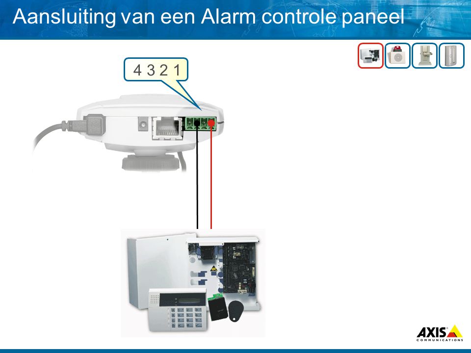
Aansluiting van een Alarm controle paneel
13
Aansluiting van een externe sirene (N.O.)
Diode Via de output op pin 4 wordt een relay geschakeld die het contact sluit voor de sirene.

14
Waarom via een relais Het doel van een relais is met een kleine hoeveelheid vermogen van bv een netwerk camera een groter vermogen te schakelen… De lagere voltage beweegt een schakel element dat contact maakt voor een veel groter vermogen. Bijvoorbeeld: U kunt met 9 volt en 100 mA een schakeling maken voor een voeding van 220V AC met 2,5 A. Denk aan een automatisch hek. The major reason for a relay in this context is to have 2 separated circuits. Alternatively it is possible to use an optic-coupler. The secondary reason is the load and voltage limitation of the driver in the camera (24V, 100mA). Relay Relay Construction Relays are amazingly simple devices. There are four parts in every relay: Electromagnet Armature that can be attracted by the electromagnet Spring In this figure, you can see that a relay consists of two separate and completely independent circuits. The first is at the bottom and drives the electromagnet. In this circuit, a switch is controlling power to the electromagnet. When the switch is on, the electromagnet is on, and it attracts the armature (blue). The armature is acting as a switch in the second circuit. When the electromagnet is energized, the armature completes the second circuit and the light is on. When the electromagnet is not energized, the spring pulls the armature away and the circuit is not complete. In that case, the light is dark. When you purchase relays, you generally have control over several variables: The voltage and current that is needed to activate the armature The maximum voltage and current that can run through the armature and the armature contacts The number of armatures (generally one or two) The number of contacts for the armature (generally one or two -- the relay shown here has two, one of which is unused) Whether the contact (if only one contact is provided) is normally open (NO) or normally closed (NC) Set of electrical contacts Relay Applications In general, the point of a relay is to use a small amount of power in the electromagnet -- coming, say, from a small dashboard switch or a low-power electronic circuit -- to move an armature that is able to switch a much larger amount of power. For example, you might want the electromagnet to energize using 5 volts and 50 milliamps (250 milliwatts), while the armature can support 120V AC at 2 amps (240 watts).
. Relay. Relay Construction. Relays are amazingly simple devices. There are four parts in every relay: Electromagnet. Armature that can be attracted by the electromagnet. Spring. In this figure, you can see that a relay consists of two separate and completely independent circuits. The first is at the bottom and drives the electromagnet. In this circuit, a switch is controlling power to the electromagnet. When the switch is on, the electromagnet is on, and it attracts the armature (blue). The armature is acting as a switch in the second circuit. When the electromagnet is energized, the armature completes the second circuit and the light is on. When the electromagnet is not energized, the spring pulls the armature away and the circuit is not complete. In that case, the light is dark. When you purchase relays, you generally have control over several variables: The voltage and current that is needed to activate the armature. The maximum voltage and current that can run through the armature and the armature contacts. The number of armatures (generally one or two) The number of contacts for the armature (generally one or two -- the relay shown here has two, one of which is unused) Whether the contact (if only one contact is provided) is normally open (NO) or normally closed (NC) Set of electrical contacts. Relay Applications In general, the point of a relay is to use a small amount of power in the electromagnet -- coming, say, from a small dashboard switch or a low-power electronic circuit -- to move an armature that is able to switch a much larger amount of power. For example, you might want the electromagnet to energize using 5 volts and 50 milliamps (250 milliwatts), while the armature can support 120V AC at 2 amps (240 watts).")
15
Voor de goede orde… Checklist
Bij twijfel altijd een ervaren installeur het werk laten doen. De camera kan als sensor dienen met zijn VMD functionaliteit Gebruik degelijke bekabeling Niet de camera output overbelasten Denk er aan een diode over de output te zetten. I/O poorten zijn betrouwbaarder in lage licht situaties dan VMD

16
Q & A

Verwante presentaties


 ° 8 en 16 kanalen (500 GB, 1 TB en 2 TB), gebruik van aparte schijven °>")


![PreSoft [relatiebeheer] Het centraal beheren van relaties en contactgegevens is de basis voor veel dagelijkse werkzaamheden. PreSoft [relatiebeheer] is.](/8/2062582/big_thumb.jpg "PreSoft [relatiebeheer] Het centraal beheren van relaties en contactgegevens is de basis voor veel dagelijkse werkzaamheden. PreSoft [relatiebeheer] is.>")


