Download de presentatie
De presentatie wordt gedownload. Even geduld aub

1
Anti Blokkeer Systeem Het anti blokkeer systeem is al enige jaren ingeburgerd in auto-rijdend Nederland. Door de jaren heen hebben zich diverse ontwikkeling voorgedaan. Echter het doel is steeds gelijk gebleven. De koersstabiliteit behouden tijdens remmen. Het systeem kan verder uitgebreid worden met een regeling die de koerstabiliteit tijdens rijden verbeterd, bv. Anti Slip Regeling (ASR) of Electronisch Stabiliteits Programma (ESP)
 of. Electronisch Stabiliteits Programma (ESP)")
2
De koerstabiliteit wordt bereikt door middel van de remmen
De koerstabiliteit wordt bereikt door middel van de remmen. Het beïnvloeden van de remdruk (tijdens remmen) kan gebeuren door vloeistof afname (volume vergroting) of door drukaanpassing (drukdaling/drukverhoging). Daarbij kan men verschillende systemen onderscheiden => Drukregeling door volumeverandering * Direct werkend * Indirect werkend => Drukregeling door drukaanpassing * Open systeem * Gesloten systeem
 kan gebeuren door vloeistof afname (volume vergroting) of door drukaanpassing (drukdaling/drukverhoging). Daarbij kan men verschillende systemen onderscheiden. => Drukregeling door volumeverandering. * Direct werkend. * Indirect werkend. => Drukregeling door drukaanpassing. * Open systeem. * Gesloten systeem.")
3
Bij drukaanpassing bestaan verschillende regelprincipes
Bij drukaanpassing bestaan verschillende regelprincipes. Een regeleenheid ontvangt daarvoor signalen welke afkomstig zijn van een aantal sensoren, belangrijk daarbij zijn de wielsnelheidssensoren. De regeleenheid stuurt magneetkleppen (solenoïdes) in het kleppenhuis aan. Er is altijd sprake van een gesloten regelkring (signaleren – ingrijpen – controleren – corrigeren). Regelprincipes
 in het kleppenhuis aan. Er is altijd sprake van een gesloten regelkring (signaleren – ingrijpen – controleren – corrigeren). Regelprincipes.")
4
De meest toegepaste systemen zijn de indirect werkende. We bespreken de
Systemen die werken volgens het gesloten systeem (meestal met een pneumatische rembekrachtiger) Systemen die werken volgens het open systeem (meestal met een hydraulische rembekrachtiger)
 Systemen die werken volgens het open systeem. (meestal met een hydraulische rembekrachtiger)")
5
Gesloten regelsysteem (drie 3/3-kleppen)
")
6
Druk doorlaten (remmen)
Tijdens remmen staan de kleppen open m.a.w. ze worden niet bekrachtigd

7
Druk vasthouden Tijdens remmen dreigt blokkeren. De kleppen worden bekrachtigd, de remdruk kan niet meer oplopen.

8
Druk aflaten De blokkeer-dreiging is nog steeds aanwezig. De druk naar de remmen moet verminderen. De kleppen worden bekrachtigd en de retourpomp drukt de vloeistof terug het remsysteem in.

12
Gesloten regel systeem (Mercedes)
Dit systeem is uitgevoerd met 8 2/2-kleppen. Hierdoor kan men een nauwkeurige regeling realiseren. Dit systeem is uitgebreid met 2 2/2-kleppen voor ASR (ETS) regeling. tijd voor een filmpje
 regeling. tijd voor een filmpje.")
13
Open regelsysteem (vijf 3/2 en drie 2/2-kleppen)
")
14
Hydraulische rembekrachtiger
Ruststand (niet remmen) Construction: The master cylinder is the center port type single master cylinder, which is used for the front brakes only. The brake booster is integrated with the master cylinder. The operating portion, master cylinder, and regulator are positioned coaxially to achieve a simple and compact construction. This construction enables the hydraulic pressure that is generated by the brake booster to be applied directly to the rear brakes. No brake pedal action: In light blue, non-pressurized brake fluid is represented, whilst darker blue represents pressurized fluid by the pump, and we will see dark blue as fluid pressurized by the action of the brake piston later. Follow the flow of fluid through the master cylinder and see that front and rear brake calipers receive fluid non-pressurized, so that bleeding air can be done by applying pressure onto the reservoir.
 Construction: The master cylinder is the center port type single master cylinder, which is used for the front brakes only. The brake booster is integrated with the master cylinder. The operating portion, master cylinder, and regulator are positioned coaxially to achieve a simple and compact construction. This construction enables the hydraulic pressure that is generated by the brake booster to be applied directly to the rear brakes. No brake pedal action: In light blue, non-pressurized brake fluid is represented, whilst darker blue represents pressurized fluid by the pump, and we will see dark blue as fluid pressurized by the action of the brake piston later. Follow the flow of fluid through the master cylinder and see that front and rear brake calipers receive fluid non-pressurized, so that bleeding air can be done by applying pressure onto the reservoir.")
15
Hydraulische rembekrachtiger
Geen achterremmen (lekkage) No booster operation: If the booster does not operate, there is no pressure applied on the rear brake cylinders. Braking is only possible on the front wheels without power assist. NO REAR BRAKE
 No booster operation: If the booster does not operate, there is no pressure applied on the rear brake cylinders. Braking is only possible on the front wheels without power assist. NO REAR BRAKE.")
16
De hoofdremcilinder bedient alleen de voorremmen
De hoofdremcilinder bedient alleen de voorremmen. De achter-remmen worden door de accumulator bediend. Een klep (P & B klep) controleert de achterremdruk en regelt zo de remkracht voor en achter. Afgebeelde hoofdremcilinder in de de stand remmen (hoge druk) REACTIEPLUNJER AANVOER (reservoir) ACCUMULATOR DRUKSTIFT REGELZUIGER REGELKLEP BUITENSTE HOOFDREMZUIGER BEKRACHTIGER KAMER BINNENSTE HOOFDREM ZUIGER REMMEN VOOR ACHTER RETOUR
 controleert de achterremdruk en regelt zo de remkracht voor en achter. Afgebeelde hoofdremcilinder in de de stand remmen (hoge druk) REACTIEPLUNJER. AANVOER (reservoir) ACCUMULATOR. DRUKSTIFT. REGELZUIGER. REGELKLEP. BUITENSTE. HOOFDREMZUIGER. BEKRACHTIGER KAMER. BINNENSTE. HOOFDREM. ZUIGER. REMMEN. VOOR. ACHTER. RETOUR.")
17
Hoofdremcilinder met bekrachtiging
Rust toestand The master cylinder consists out of one single portless type. Over a master cylinder return spring a booster piston is acting on a spool valve which controls the pressure coming from the accumulator applied as boost pressure to the booster piston to assist braking force Lets take a closer look: NO brake pedal action In light blue un-pressurized brake fluid is present, darker blue pressurized fluid by the pump and later we will se dark blue as fluid pressurized by the action of the brake piston. Follow the flow of fluid through the master cylinder and see that front and rear brake calipers receive fluid un-pressurized, so that bleeding air can be done by applying pressure onto the reservoir. 16

18
Hoofdremcilinder met bekrachtiging
Remdruk opbouwen When brake force is applied to the brake pedal, the master cylinder is moved to the right against return spring force. The valve closes the pressure chamber of so no fluid can return to the reservoir. Further action of the master brake piston pressurizes the fluid to the front wheels but acts also on the booster piston,which pushes the spool valve to the left against return spring force. This opens the passage of the pressurized fluid from the acc. to the booster chamber and runs around the master cylinder to the front of the master piston to assist the force acting on the master piston. Th same pressure is also applied on the rear wheels.

19
Hoofdremcilinder met bekrachtiging
Remdruk constant houden The pressure from the acc. over the spool valve acts also on a reaction disc, which generates a force to the reaction rod acting against the right movement of the spool valve. The two forces (from brake pedal which brake assistance and reaction rod force) become in balance due to the control in the spool valve. Applying more brake pedal force, will create more booster pressure, more brake assistance to the front brakes and more pressure direct to the rear brakes.
 become in balance due to the control in the spool valve. Applying more brake pedal force, will create more booster pressure, more brake assistance to the front brakes and more pressure direct to the rear brakes.")
20
Hoofdremcilinder met bekrachtiging
Remdruk verminderen What happens when finally the brake pedal is released, the return spring of master piston and booster piston pushes the pistons to the right thus closing of the pressure from the acc. to the booster chamber over the spool valve and open the passages to the reservoir so pressure can escape.

21
ABS-actuator - magneetkleppen
Based on the signals received from the 4 wheel speed sensors, the skid control ECU calculates each wheel speed and deceleration, and checks wheel slipping conditions. And according to the slipping condition, the ECU controls the pressure holding and reduction valves in the actuator in order to adjust the fluid pressure of each wheel cylinder in the following 3 modes: Pressure increase, Pressure hold, Pressure reduction

22
Druk doorlaten (remmen)
Tijdens remmen staan de kleppen open m.a.w. ze worden niet bekrachtigd. De achterremmen worden door de accumulator bediend.

23
Druk regelen (individueel)
* Één voorwiel kan voldoende rem-kracht overbrengen. * De achterwielen dreigen te blokkeren (druk verminderen). * Één voorwiel neigt tot blokkeren (druk houden).
. * Één voorwiel neigt tot blokkeren (druk houden).")
24
Vragen?

25
TRC (TRactio Controle)
ABS & TRC actuator on GS300 1: accumulator cut off solenoid valve (STR) 2: booster pressure cut off solenoid valve for the rear wheel cylinders (SA3) 3: Master cylinder cut off solenoid valve for front (left) wheel. (SA1) 4: Master cylinder cut off solenoid valve for front (right) wheel. (SA2) 2 1 3 4 In combination with the hydraulic brake booster and the 8 2-position solenoids of the ABS, one additional solenoid valve for rear wheel brake master cylinder (booster pressure) cut-off solenoid (SA3) and one accumulator cut-off solenoid (STR) valve is used. When wheel slip is detected, the accumulator solenoid valve opens to apply hydraulic pressure via the pressure holding and reduction solenoids to the rear wheel brakes. (master cylinder cut-off solenoid SA3 is closed) Further control of wheel slip is performed by the ABS. NOTE: One of the rear brakes are in reduction mode Achteras Vooras
 2: booster pressure cut off solenoid valve for the rear wheel cylinders (SA3) 3: Master cylinder cut off solenoid valve for front (left) wheel. (SA1) 4: Master cylinder cut off solenoid valve for front (right) wheel. (SA2) In combination with the hydraulic brake booster and the 8 2-position solenoids of the ABS, one additional solenoid valve for rear wheel brake master cylinder (booster pressure) cut-off solenoid (SA3) and one accumulator cut-off solenoid (STR) valve is used. When wheel slip is detected, the accumulator solenoid valve opens to apply hydraulic pressure via the pressure holding and reduction solenoids to the rear wheel brakes. (master cylinder cut-off solenoid SA3 is closed) Further control of wheel slip is performed by the ABS. NOTE: One of the rear brakes are in reduction mode. Achteras. Vooras.")
26
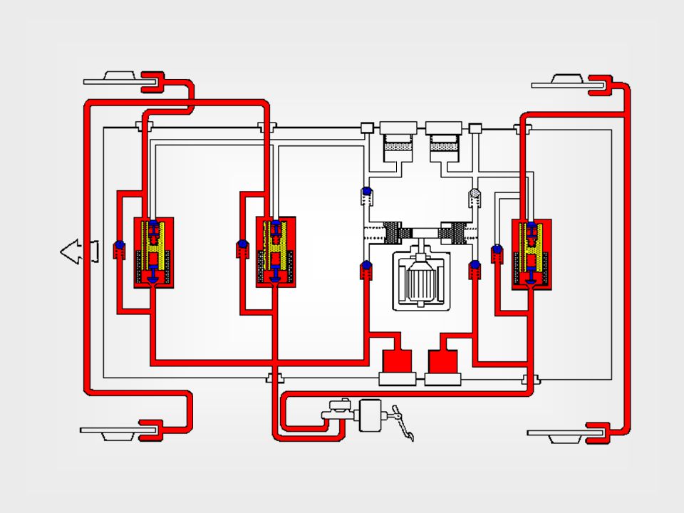
Actuator tijdens weinig onderstuur - GS
VSC (Vehicle Stability Controle) Actuator tijdens weinig onderstuur - GS Brake hydraulic circuit is split by axles Accumulator cut solenoid valve STR Booster pressure cut off solenoid valve for rear SA3 SA1 SA2 Druk-houd kleppen Pressure from the accumulator is used, guided through the accumulator cut solenoid valve (sometimes indicated STR), which is then applied to the rear wheel brakes. Holding and reduction solenoid valves control the brake pressure. NOTE: On the above slide, the inner rear brakes are in the reduction mode. Pressure reduction mode Druk-aflaat kleppen binnen buiten Achterwielen Voorwielen
 Actuator tijdens weinig onderstuur - GS. Brake hydraulic circuit is split by axles. Accumulator cut solenoid valve STR. Booster pressure cut off solenoid valve for rear SA3. SA1. SA2. Druk-houd kleppen. Pressure from the accumulator is used, guided through the accumulator cut solenoid valve (sometimes indicated STR), which is then applied to the rear wheel brakes. Holding and reduction solenoid valves control the brake pressure. NOTE: On the above slide, the inner rear brakes are in the reduction mode. Pressure reduction mode. Druk-aflaat kleppen. binnen. buiten. Achterwielen. Voorwielen.")
27
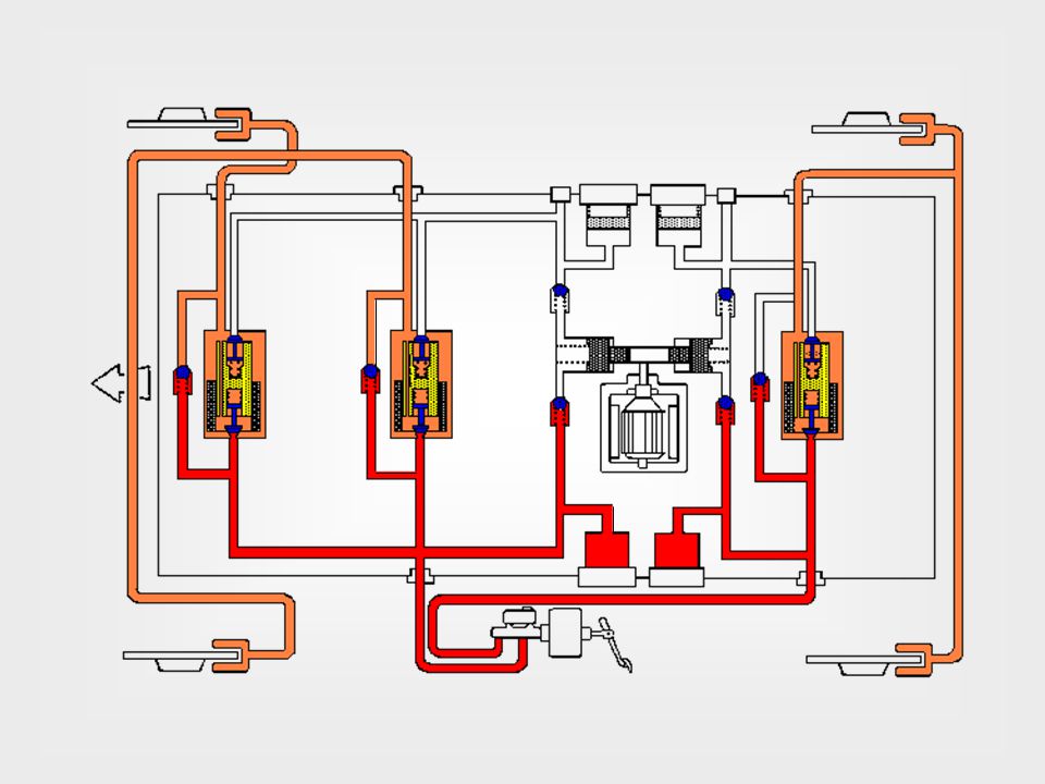
Actuator tijdens hevige onderstuur - GS
VSC (Vehicle Stability Controle) Actuator tijdens hevige onderstuur - GS Brake hydraulic circuit is split by axles Accumulator cut solenoid valve STR Booster pressure cut off solenoid valve for rear SA3 SA1 SA2 Pressure reduction mode Druk-houd kleppen Pressure increase mode Pressure from the accumulator is used, guided through the accumulator cut solenoid valve (sometimes indicated STR), which is then applied to the rear wheel brakes. Holding and reduction solenoid valves control the brake pressure. NOTE: On the above slide, the inner rear brakes are in the increase mode, the outer rear brake cylinders are in reduction mode. Druk-aflaat kleppen binnen buiten Achterwielen Voorwielen
 Actuator tijdens hevige onderstuur - GS. Brake hydraulic circuit is split by axles. Accumulator cut solenoid valve STR. Booster pressure cut off solenoid valve for rear SA3. SA1. SA2. Pressure reduction mode. Druk-houd kleppen. Pressure increase mode. Pressure from the accumulator is used, guided through the accumulator cut solenoid valve (sometimes indicated STR), which is then applied to the rear wheel brakes. Holding and reduction solenoid valves control the brake pressure. NOTE: On the above slide, the inner rear brakes are in the increase mode, the outer rear brake cylinders are in reduction mode. Druk-aflaat kleppen. binnen. buiten. Achterwielen. Voorwielen.")
28
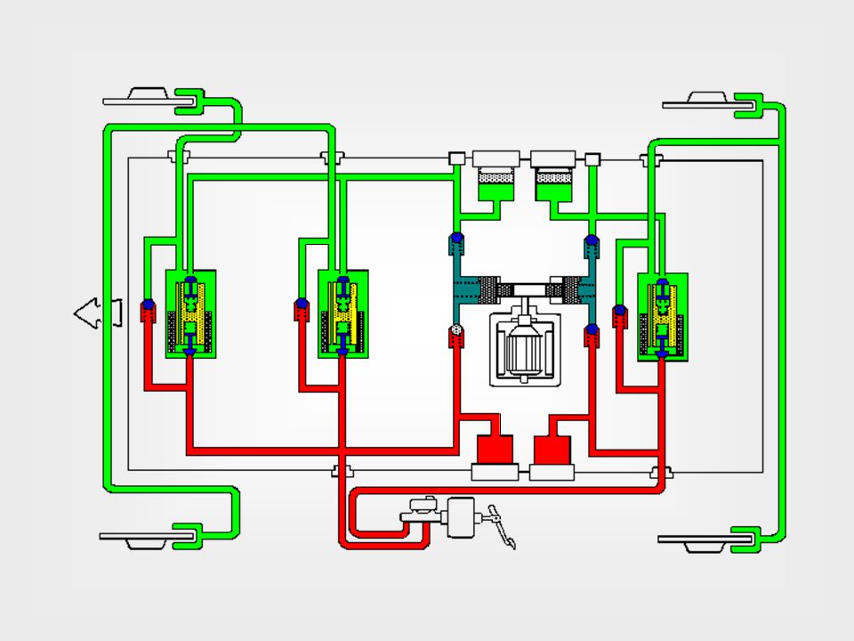
Actuator tijdens overstuur - GS
VSC (Vehicle Stability Controle) Actuator tijdens overstuur - GS Brake hydraulic circuit is split by axles Accumulator cut solenoid valve STR Booster pressure cut off solenoid valve for rear SA3 SA1 SA2 Pressure holding mode Pressure increase mode Druk-houd kleppen Due to the inner lay-out of the actuator, on the GS brake pressure needs to be stopped from going to the front wheel brakes by the holding valves. Solenoid valve SA3/SA2 supplies brake pressure to the left or right front wheel, depending on the turning direction. The holding valves for the rear wheels control, if and how much, brake pressure can be applied to the rear brakes. During normal braking: all solenoid valves are turned off, STR closed, SA1, SA2, SA3 open. VSC active: STR open (ON), SA1, SA2, SA3 closed (ON). Druk-aflaat kleppen Pressure reduction valve buiten binnen binnen buiten Achterwielen Voorwielen
 Actuator tijdens overstuur - GS. Brake hydraulic circuit is split by axles. Accumulator cut solenoid valve STR. Booster pressure cut off solenoid valve for rear SA3. SA1. SA2. Pressure holding mode. Pressure increase mode. Druk-houd kleppen. Due to the inner lay-out of the actuator, on the GS brake pressure needs to be stopped from going to the front wheel brakes by the holding valves. Solenoid valve SA3/SA2 supplies brake pressure to the left or right front wheel, depending on the turning direction. The holding valves for the rear wheels control, if and how much, brake pressure can be applied to the rear brakes. During normal braking: all solenoid valves are turned off, STR closed, SA1, SA2, SA3 open. VSC active: STR open (ON), SA1, SA2, SA3 closed (ON). Druk-aflaat kleppen. Pressure reduction valve. buiten. binnen. binnen. buiten. Achterwielen. Voorwielen.")
29
Remdrukregelprincipes
Twee-faseregeling klepconfiguratie tijd wielremcilinderdruk ideale waarde Twee-faseregeling met mogelijkheid tot langzame drukverhoging tijd wielremcilinderdruk klepconfiguratie ideale waarde

30
Driefaseregeling (drukhouden na drukverlaging)
Remdrukregelprincipes Driefaseregeling (drukhouden na drukverlaging) klepconfiguratie ideale waarde wielremcilinderdruk tijd Vierfaseregeling (drukhouden na drukverhoging en drukverlaging) door pulserende klepsturing ideale waarde klepconfiguratie tijd wielremcilinderdruk
 klepconfiguratie. ideale waarde. wielremcilinderdruk. tijd. Vierfaseregeling (drukhouden na drukverhoging en drukverlaging) door pulserende klepsturing. ideale waarde. klepconfiguratie. tijd. wielremcilinderdruk.")
31
Vierfaseregeling met mogelijkheid tot langzame drukverhoging
Remdrukregelprincipes Vierfaseregeling met mogelijkheid tot langzame drukverhoging klepconfiguratie ideale waarde wielremcilinderdruk tijd ideale waarde klepconfiguratie tijd wielremcilinderdruk Vierfaseregeling met langzame drukaanpassing door pulserende klepsturing

32
Proportionele regeling
Remdrukregelprincipes Proportionele regeling klepconfiguratie ideale waarde wielremcilinderdruk tijd

33
DIRECT WERKEND DOOR EEN SCHEIDINGS-ZUIGER MET EEN GROOT EN KLEIN OPPERVLAK EN EEN STERKE VEER (DIE NIET BIJ VOLLE REMDRUK KAN WORDEN INGEDRUKT) WORDT MET EEN MAGNEETKLEP DE DRUK OP DE ZUIGER BEÏNVLOED. HIERDOOR KUNNEN DE REGELING; * DRUKHOUDEN, * DRUKVERLAGEN EN * DRUKVERHOGING NAAR DE WIELREM-CILINDER GEREALISEERD WORDEN. HET SYSTEEM REGELT ERG GROF. WIELREM CILINDER HOOFDREMCILINDER VOLUMEREGELAAR MET ZWARE VEER VOEDINGSEENHEID ELEKTRONISCHE REGELEENHEID
 WORDT MET EEN MAGNEETKLEP DE DRUK OP DE ZUIGER BEÏNVLOED. HIERDOOR KUNNEN DE REGELING; * DRUKHOUDEN, * DRUKVERLAGEN EN * DRUKVERHOGING. NAAR DE WIELREM-CILINDER GEREALISEERD WORDEN. HET SYSTEEM REGELT ERG GROF. WIELREM CILINDER. HOOFDREMCILINDER. VOLUMEREGELAAR MET ZWARE VEER. VOEDINGSEENHEID. ELEKTRONISCHE REGELEENHEID.")
34
INDIRECT WERKEND HOOFDREMCILINDER VOLUMEREGELAAR MET SCHEIDINGSZUIGER VOEDINGSEENHEID ELEKTRONISCHE REGELEENHEID DOOR EEN SCHEIDINGS-ZUIGER IS DE VOLUMEREGELAAR IN VIER KAMERS VERDEELD HET SYSTEEM SCHAKELD PERMANENT TUSSEN HOOFDREMCILINDER EN WIELREMCILINDER WORDT o.a.TOEGEPAST BIJ HONDA WIELREMCILINDER

35
OPEN SYSTEEM VOEDINGSEENHEID DE DRUKVERLAGING VINDT PLAATS DOOR VLOEISTOF NAAR HET RESERVOIR TE STUREN DRUKVERHOGING GEBEURT DOOR EEN APART DRUKREGEL-SYSTEEM MET EEN APARTE POMP. HET SYSTEEM WORDT GEPRODUCEERD DOOR ATE (bv. type mark II) WIELREMCILINDER HOOFDREM-CILINDER HYDRAULISCHE REMBEKRACHTIGER
 WIELREMCILINDER. HOOFDREM-CILINDER. HYDRAULISCHE REMBEKRACHTIGER.")
36
GESLOTEN SYSTEEM DE DRUKVERLAGING VINDT PLAATS DOOR VLOEISTOF OP TE SLAAN IN EEN BUFFER EN TERUG TE STUREN NAAR HET REMSYSTEEM DRUKVERHOGING GEBEURT DOOR EEN APART DRUKREGEL-SYSTEEM MET EEN APARTE POMP. HET SYSTEEM WORDT GEPRODUCEERD DOOR o.a. BOSCH WIELREMCILINDER HOOFDREMCILINDER

Verwante presentaties