Download de presentatie
De presentatie wordt gedownload. Even geduld aub

1
Tussen sensor en (computer)syteem
Van Analoog Digitaal Van Digitaal Analoog Sensorelektronica

2
Analog Digital Conversion
Properties: Resolution & precision number of bits Conversion time max. sample frequency Price

3
Precision Aantal bits Aantal ‘stappen’ Nauwkeurigheid 8 10 12 14 16384
0.006% 16 65536 0.0015%

4
Precision Meneer, mijn computer is 16 bits en mijn
Aantal bits Aantal ‘stappen’ Nauwkeurigheid 8 256 0.4 % 10 1024 0.1 % 12 4096 0.025 % 14 16383 0.006 % 16 65536 % Meneer, mijn computer is 16 bits en mijn ADC maar 12 bits. Hoe nu verder?

5
Laagst mogelijke sample frequentie: 2 samples per periode
Sample frequency Aliasing Laagst mogelijke sample frequentie: 2 samples per periode

6
Analoog Digitaal Conversion
Principes Successive Approximation Flash ADC Sigma-Delta ADC

7
Sample & Hold Amplifier

9
Successive Approximation

10
Flash ADC Hoeveel comparatoren zijn er nodig voor een 10-bits ADC? 5
3,5 2,5 1,5 0,5 2 1 + - Hoeveel comparatoren zijn er nodig voor een 10-bits ADC?

11
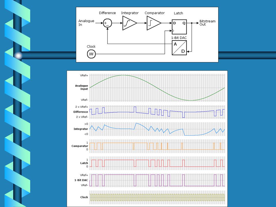
Sigma-Delta ADC

12
Sigma-Delta modulator

14
SigmA Delta Converter type HI7190
Sample frequency: 10MHz, , 24 - Bit, High Precision, 22 - Bits Resolution

15
Resolution and Bandwith

16
Digitaal Analoog (DAC)
DAC met R – 2R weerstanden Pulsbreedte modulatie (PWM)
")
17
Wet van Ohm V = I * R I = V / R

18
Operational Amplifier

19
Optelschakeling OpAmp
IR = ? IR = ? 1 k 1 k 1 V 2 k 0 Volt IR = ? Bereken Vo

20
Optelschakeling OpAmp
1 mA 1 V 1.5 mA 2 k 0 Volt 0.5 mA -1.5 V

21
DAC 1 Ropamp = 1 k I8k = I1k = Itotaal = Bereken V0 =
LSB = onderste of bovenste weerstand? DAC 4 V 1 IR = ? 0 V (virtueel) IR = ?
 IR =")
22
Waarom is deze methode niet nauwkeurig?
DAC Ropamp = 1 k I8k = 0,5 mA I1k = 4 mA Itotaal = 4,5 mA V0 = -4,5 V LSB = bovenste weerstand 4 V 1 IR = ? 0 V (virtueel) IR = ? Waarom is deze methode niet nauwkeurig?
 IR = Waarom is deze methode niet nauwkeurig")
23
DAC met R-2R netwerk

24
Pulse Width Modulation
Digital Analog Converter Toepassing: servo-motorregeling Modulation frequency Duty Cycle = verhouding hoog/laag

25
Pulse Width Modulation
Digital Analog Converter Toepassing: servomotorregeling Volt Volt Volt Modulation frequency > 600 Hz (hangt van de traagheid van de motoras) Duty Cycle = verhouding hoog/laag
 Duty Cycle = verhouding hoog/laag.")
26
Sensors & Data Acquisition Systems
Amplifiers & Analog Filters Sample & Hold ADC

27
Transducers Sensors Small Signals Signal Conditioning Wiring/Grounding
Phenomena ADC Transducers Sensors Small Signals Signal Conditioning Wiring/Grounding

28
Voorbeeld van een sensor: rekstrookje
R = weerstand = soortelijke weerstand L = lengte A = doorsende

29
Strain Gauge

30
Applications Force sensors Spiro meters Truck weigh stations
Position sensors

31
Force to Voltage: Weatstone Bridge Circuit
R1= R2= RG1= RG2 = 1000 ; RG MAX= 10 ; VEX = 5 V

32
Strain Gauge (Rekstrookje)
Dummy Gauge:Temperature compensation

33
Intermezzo on Cascaded Resistors
Vin Vout R1 R2

34
Intermezzo on Cascaded Resistors
Vin Vout R1 R2

35
Force to Voltage: Weatstone Bridge Circuit
In rust: R1= R2= RG1= RG2 = 1000 ; RG MAX= 10 ; VEX = 5 V

36
Assignment: Calculate the differential input voltage for the ADC
In rust: R1= R2= RG1= RG2 = 1000 ; RG MAX= 10 ; VEX =Vin= 5 V

37
Assignment: Calculate the differential input voltage for the ADC
In rust: R1= R2= RG1= RG2 = 1000 ; RG MAX= 10 ; VEX =Vin= 5 V

38
Sensor, Amplifier & ADC Amplifier Weatstone bridge + A ADC - mV/bit?

39
Assignment: Specify the gain of the amplifier
Input range of the ADC = 5 V The ADC = 12 bit

40
The ideal Amplifier 1. Gain--infinite 2. Input impedance--infinite
3. Output impedance—zero 4. Bandwidth--infinite

41
Assignment: Design the amplifier
Voor Weatstone bridge: versterker met differentiële ingangen nodig. Dus geen van beide signaalingangen mag met de aarde worden verbonden

42
ADC Sensor Vsensor VADC
Algemene beschrijving van een systeem bestaande uit en sensor, aangesloten op een ADC ADC Sensor Rsensor Vsensor VADC RADC

43
Measurement errors - t.g.v. mismatch sensor-output-ADC-input- resistance t.g.v. aardlussen t.g.v. te lage “CMRR”

44
Sensor output resistance
Strain Gauge Vs = 50 mV; Rs = 1000 Thermocouple Rs < 20 pH Electrode Rs = 100 M

45
Rsensor RADC Error (%) 10 k 1 M 1 1 k 100 k 2 100 3 50 k 4
Assignment: Determine the measurement error as a result of the mismatch sensor-resistance and the ADC input-resistance Rsensor RADC Error (%) 10 k 1 M 1 1 k 100 k 2 100 3 50 k Sevo motor potmeter ADC PIC’s 16F876 4
 10 k 1 M 1. 1 k 100 k k Sevo motor potmeter. ADC PIC’s 16F")
46
Rsensor RADC Error (%) 10 k 1 M 1 1% 1 k 100 k 2 100 3 1‰ 50 k
Assignment: Determine the measurement error as a result of the mismatch sensor-resistance and the ADC input-resistance Rsensor RADC Error (%) 10 k 1 M 1 1% 1 k 100 k 2 100 3 1‰ 50 k Sevo motor potmeter ADC PIC’s 16F876 4 500%
 10 k 1 M 1. 1% 1 k 100 k 3. 1‰ 50 k Sevo motor potmeter. ADC PIC’s 16F %")
47
Measurement error t.g.v. mismatch sensor-output-ADC input- resistance
Stel: 10 bits ADC - Wat is de resolutie? Bij welke van de 4 sensoren is de fout > 1 bit? Zijn de berekende errors absoluut of relatief? Hoe kunnen deze fouten opgelost worden? Hardwarematig ….? Softwarematig …..?

48
Measurement error t.g.v. mismatch sensor-output-ADC input- resistance
Stel: 10 bits ADC - Wat is de resolutie? 1 : 1024 De berekende errors zijn relatief? Hoe kunnen deze fouten opgelost worden? Softwarematig Ja!

49
Bij welke van de 4 sensoren is de fout > 1 bit?
Rsensor RADC Error (%) 10 k 1 M 1 1% = 3 bits 1 k 100 k 2 100 3 1‰ = 1 bit 50 k Sevo motor potmeter ADC PIC’s 16F876 4 500%
 10 k 1 M 1. 1% = 3 bits. 1 k 100 k 3. 1‰ = 1 bit. 50 k Sevo motor potmeter. ADC PIC’s 16F %")
50
Measurement errors - t.g.v. mismatch sensor-output-ADC input- resistance t.g.v. aardlussen t.g.v. te lage “CMRR”

51
Ground-Referenced Floating Signal Source

52
Grounded Measurement System

53
Floating / Differential Input Measurement System

54
Grounded Signal source Grounded Measurement System aardlus

55
Grounded Signal Source Floating Measurement System

56
Floating Source/ Floating Measurement System
R1 = R2 (10k < R < 100k)
")
57
Instrumentation Amp.

58
Common mode & Differential mode
5 V A = 200 2.525 V 2.475 V 5.0 V Common mode = 2.5 V Differential mode = 50 mV

59
Common Mode Rejection Ratio (CMRR)Beter 20 log
ingangsbereik ADC = 0 – 5 Volt; Versterkingsfactor 200; 12 bits ADC Eis: fout mag max. 1 bit zijn. 12 bits ADC 1 : 4096; 1 LSB = 5000 mV/4096 = 1,25 mV. Bij ingang versterker is dit 1,25/200 = 6,25 V CMRR (dB) = 20 log (Differential mode/ Common Mode) = 20 log ( 6,25 V / 10V) 100 dB. (factor 10000) 20 dB = factor 10
 = 20 log (Differential mode/ Common Mode) = 20 log ( 6,25 V / 10V) 100 dB. (factor 10000) 20 dB = factor 10.")
60
Toepassing Unshielded Twisted Pair EMS

61
No comment

Verwante presentaties


 Quiz Night !>")
 Synthesis Output = sinusvormig signaal Maximum frequentie = ½ klokfrequentie.>")


